To model a mixed mode system you will need to have set up mixed mode aperture types in the source building. These spaces will be cooled to 27 degrees C. The cut-off temperature should not be higher than 25 degrees C to ensure that the apertures will be fully closed at 26 degrees C.
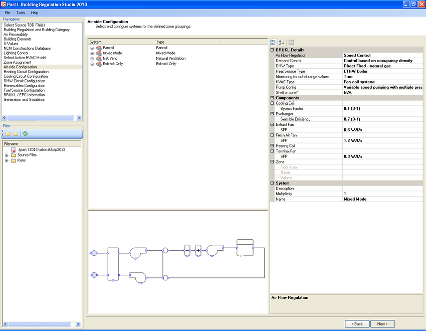
The bypass factor determines the proportion of air that will pass through the cooling coil and therefore how much air will bypass it altogether. It is commonly used to express the efficiency of a cooling coil. If the contact factor is known then the bypass factor can be calculated using the following relationship: Bypass Factor = 1 - Contact Factor.
If a zone in the actual building is specified as fancoil heating only, mechanical ventilation with or without recirculated air, mixed mode (such as in this example), natural ventilation, or occupied and unheated, then the same zone in the notional building will be modelled with the same level of servicing. Otherwise it will be modelled as fancoil or CAV, depending on which system would use the least fan energy.
For zones where the ventilation system provides heating, cooling, or heating and cooling the terminal fan SFP will be 0.3 W per l/s and the SFP in the central AHU will be 1.8 W per l/s.
The notional building will have heat recovery with sensible efficiency of 70% for zones with mechanical ventilation providing supply and extract. The heat recovery will be switched off when the air-side system is in cooling mode.
Monitoring for out-of-range values set to True will reduce the heating, cooling, auxiliary, and HWS consumption by 5%.
Exercise and Notes
Set the bypass factor to 0.1.
The terminal fan SFP has been specified as 0.3 W per l/s.
The extract fan will be modelled with an SFP of 0.6 W per l/s.
The fresh air fan will be producing 1.2 W per l/s.
These zones will benefit from demand control ventilation as a function of occupancy density where air flow will be regulated by fan speed as opposed to dampers. The auxiliary energy will be adjusted accordingly. A revised fresh air rate will be calculated using Equation 13 of the NCM where the demand control coefficient will be 0.85 per Table 14. The notional building will be modelled in a similar fashion (as described in the Setting Up a Fancoil System topic).
Monitoring for out-of-range values = True.