The Heating Plantroom Controls options provide for the specification of centralized building control functions and the building's infiltration characteristics. They give you control over frost protection and optimum start settings for your model. Without using these settings, Tas will assume that all of the heating occurs in the first hour of the day that the heating is on, so you will have a large spike in the heating load at this time. If you want to smooth out the heating load you can use the options here.
Infiltration Coefficient
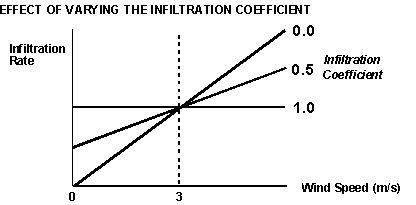
The Infiltration Coefficient provides a facility for making fresh air infiltration dependent on wind speed. The diagram below illustrates the relationship between infiltration and wind speed for 3 different values of the Infiltration Coefficient.

The infiltration rate specified in the internal conditions is assumed to occur when the wind speed is 3 m/s. The infiltration coefficient specifies the factor by which this value is reduced at a wind speed of zero. For other wind speeds the infiltration is calculated by linear interpolation or extrapolation from the two specified points.
Setting the infiltration coefficient to 1 thus produces a horizontal straight line relationship between infiltration and wind speed. This means that the infiltration rate is fixed at the rate specified in Internal Conditions for all wind speeds.
Setting the coefficient to zero produces a relationship of direct proportionality such that at 0m/s wind speed the infiltration will be zero and at 3 m/s the infiltration rate will be that set in the internal conditions. When the coefficient is set to a value between 0 and 1 a proportion of the infiltration at 3 m/s will be assumed to occur at 0m/s wind speed. For example, if the coefficient is set to 0.5, 50% of the infiltration which occurs at 3 m/s will be assumed to occur at 0m/s wind speed. The proportion of infiltration which occurs at 0m/s wind speed can be attributed to the stack effect.
Master Control Zone
This facility allows for a single nominated zone (the Master Control Zone) to have control over all other zones (the "slave zones"). When the master control zone is set by entering a value number into the box, that zone will be controlled according to its own specifications in the internal conditions. All other zones will be forced to take the same proportion of emitter output as the control zone. For example, if the control zone requires 50% of its installed heat emitter capacity to control its internal environment, then all the other zones will be forced to draw 50% of their installed heat emitter capacity. The same principle applies for cooling. This facility can be used to select heating zone arrangements by demonstrating the implications on environmental quality and energy consumption of locating thermostats in various zones.
If a zero is entered into the box, then each zone will be individually controlled.
Warning - Master control Zone cannot be specified if the Zone Maximum Load (for heating or cooling) are set to 'SIZING' or 'DESIGN SIZING'.
Warning - External compensation does not operate in slave zones.
FP/OS Control Zone
(Frost Protection/Optimum Start Control Zone) this facility will allow for a single nominated zone to control the operation of internal frost protection and optimum start. These functions are explained below.
If a '0' is entered into the box then no internal frost protection or optimum
start will operate.
Both Master Control Zone and Frost Protection/Optimum Start Control
Zone may be set concurrently, provided they are set to the same
zone number.