
A plane will set the height of points, walls, and spaces. A plane will be applied usually to ceiling and floor surfaces, but you will also be able to apply the plane to walls or points. Applying a plane to a wall will raise or lower it perpendicular to the building plan so the wall itself will not be sloped. You can't actually slope a wall in Tas but you can model buildings which do have sloped walls. You just need to incline the floor or ceiling surface and then apply a wall construction type, for example "External Wall", to the sloped surface.
On the Tools menu, point to New 3D Plane, and then select a plane type:
By Points
In a 2D plan view, where two walls with different orientations meet or intersect, the software will allow you to select the resulting node, or point of intersection. This will be done by using the Select End tool. In the Cartesian coordinate system three non-colinear points will define a plane. You have to select three such points to be able to use the "by points" function. Multi-select will be triggered by holding down the Ctrl key on the keyboard, allowing you to select more than one point.
Complete the "Plane by Points" dialog and then click OK to add the plane to the file. You will still have to apply the plane to a surface for it to take effect. The plane can be applied to a surface by using the "Select Space" tool and by clicking Height on the context menu, which will open by right-clicking within the space/room.
On the Space Heights dialog choose whether to apply the plane to the ceiling (on the Ceiling Height tab) or the floor (on the Floor Height tab). Clear the "Use default wall height of current floor" checkbox, and then click on the down-arrow for "Select plane to calculate". Choose a plane from the drop-down list and then click on the "Apply" button to preview the plane in a 3D floors view.
Click OK to apply the plane, or click Cancel to close the dialog without applying the plane.
| Name | Enter a name for the plane, which can't be the same as another
plane but it can contain any combination of letters, numbers,
and characters.
As the plane is only going to be added to the file at this time, and you may need to create a number of planes overall, the name will help you to identify which plane you are going to apply to the surfaces later on. |
| Height A wrt [Ground Floor] | Enter the perpendicular distance by which you want to raise
point A above the level of the floor.
The height defaults to the default wall height of the current floor (as determined by the Floors dialog). |
| Height B | Enter the height of point B, following the same logic as for point A. |
| Height C | Enter the height of point C, following the same logic as for points A and B. |
Here's an example of how to use a single plane to slope a roof over two floor levels. The same principle can be used to produce a continuous slope over multiple floors.
Click on the thumbnails to enlarge the images. In this first screenshot, an arbitrary area is drawn on the ground floor with a default height of 3.0m.
A first floor is then added to the file, situated directly above the ground floor.

Walls on the ground floor are copied up to the first floor.

On the ground floor, three points are selected with the Select End tool.

Point heights are input on the Plane by Points dialog box. Points A and B on the western wall are raised to 6.0m above the ground floor. The new plane is added to the file but not to the geometry.

The ground floor is divided into two equal areas, the ceiling surface of the eastern area is raised according to the plane. Note that the area of the inclined plane is actually larger than the area to which it is applied. This is perfectly fine to do and illustrates how a single plane can be used to produce a continuous slope over multiple floors.

The dividing wall on the ground floor is now copied up to the first floor. The ceiling surface of the western area is inclined according to the same plane. Again, the area of the entire plane is larger than the area to which it is applied.
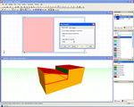
On the first floor, the eastern walls are deleted.

The end result is a continuous slope on both the first and ground floors, with the highest point being 6m above the ground.

By Inclination
Select a wall in a 2D plan view to enable the "by inclination" function. On the Plane by Inclination dialog, enter a name in the Name combo box, and then enter an angle in degrees in the Inclination text box.
The plane is rotated about the selected wall, subtending the angle that you've entered. To rotate the plane about a line directly above or below the wall, type in a perpendicular offset in the Height text box; the height will be measured with respect to the floor height and the line itself is assumed to be parallel to the selected wall.
Click on the Apply button to see a green wire line illustration of the plane.
As with the plane by points method, defining a plane "by inclination" does not apply the plane to any surface. As before, apply the plane using the "Select Space" tool and then click Height on the context menu, which opens by right-clicking in the space/room.
On the Space Heights dialog, choose whether to apply the plane to the ceiling (on the Ceiling Height tab) or the floor (on the Floor Height tab). Clear the "Use default wall height of current floor" checkbox and click on the down-arrow for "Select plane to calculate". Choose a plane from the drop-down list and click on the Apply button to preview the plane in a 3D floors view.
Click OK to apply the plane, or click Cancel.
| Name | Enter a name for the plane. It must be unique and can contain any combination of letters, numbers, and characters. The name will later enable you to identify easily which plane you are applying to a surface. |
| Height wrt [First Floor] | Enter an offset above or below the selected wall about which the plane is rotated. |
| Inclination (degrees) | The angle through which the plane rotates with respect to the selected wall. |
Offset
You must create at least one plane either "by points" or "by inclination" in order to create a plane "by offset". An offset plane is defined based on an existing plane but with a perpendicular offset. Open the Plane by Offset dialog and enter a name by which you want to identify the new plane. Click on the down arrow on the drop-down list to select an existing plane. Enter an offset measured perpendicular to the original plane to define the coordinates of the offset plane.
Defining a plane by offset does not apply the plane to a surface. As before, apply the plane using the "Select Space" tool and click Height on the context menu, which opens by right-clicking in the space/room. On the Space Heights dialog, choose whether to apply the plane to the ceiling (on the Ceiling Height tab) or the floor (on the Floor Height tab). Clear the "Use default wall height of current floor" checkbox and click on the down arrow for "Select plane to calculate". Choose a plane from the drop-down list. Click on the Apply button to preview the plane in a 3D floors view.
Click OK to apply the plane, or click Cancel.
| Name | Enter a name for the plane. It must be unique. |
| Original Plane | |
| Select Plane (drop-down list) | Choose a plane on which the offset plane is defined, based on the perpendicular distance between the original and offset planes. |
| Perpendicular Offset | Enter an offset measured perpendicular to the original plane to define the coordinates of the offset plane. |