The Building Summary contains general information about the building. Some of it will be taken from the geometry that you will have drawn in the 3D Modeller, such as the number of zones and building elements. The rest of it you will enter yourself. Many of the fields are optional.
Client
The name of the client for whom the work is being carried out.
Engineer (1), Engineer (2)
The names of two engineers who are responsible for carrying out the work.
Number of Zones
The number of zones in the building. A zone is a sub-division of the building, regarded as homogeneous for the purposes of thermal simulation. This parameter will automatically be assigned and you will not be able to edit it without re-zoning the geometry in the T3D file and then merging the changes that you have made with the TBD.
Number of Building Elements (non-editable)
The number of building elements (also known as "construction types") used by the Building Simulator. This value will change if you manually add building elements within the TBD.
Number of Apertures (non-editable)
The number of apertures in the building that allow air to flow through them. Surfaces are set as apertures using the Aperture Types facility in the Building Simulator. Surfaces which are made of the <null> building element will automatically be set as apertures.
Number of Preconditioning Days
When Tas performs a dynamic simulation it will require a starting point for the analysis. The starting point assumed in Tas will be a steady-state condition corresponding to an inside air temperature of 18 deg. C in all zones, and an outside air temperature set to the value read from the weather file for the first hour of the simulation. It takes some time for the effects of these starting assumptions to become negligible, so it is advisable to start the simulation a few days in advance of the date when the first output is required. The extra simulation days constitute the preconditioning period.
A minimum of 15 days preconditioning is recommended for all buildings.
A heavyweight building might require a preconditioning period of 30 days.
The function of the preconditioning days is to acclimatize your model
to the weather period you have chosen for the simulation. If you are unsure
of the number of preconditioning days to use, try a range of alternatives
and look for significant changes in results. Choose the minimum number
of days beyond which no significant difference in results occurs.
Building Description
Input a description of the building and add comments that are relevant to the function of the model.
The following parameters are used in the analysis of wind pressure around the model for bulk air flow simulation and to account for solar reflection from the ground.
Ground Solar Reflectance
The proportion of direct and diffuse incident solar radiation reflected by the ground in the vicinity of the building. This value will default to 0.2 which is a typical reflectance.
Building Height (non-editable)
This parameter and the four others which follow relate to the aperture air flow analysis facility. They are used in the calculation of wind pressure on the external surfaces of the building. The Building Height is set by the 3D Modeller. It is the height of the highest part of any zoned space.
Building Height Adjustment Factor
This parameter allows you to adjust the building height used in the wind pressure calculations if the Building Height provided by 3D Modeller is judged to be inappropriate. The height used in the wind pressure calculations is the Building Height multiplied by the Building Height Adjustment Factor.
Mean Height of Surroundings
This parameter lets you make allowance for the wind-shading of the building by nearby buildings or other local obstructions. If a Wind Pressure Coefficient File is specified, this parameter will be ignored.
Terrain Type (Open, Rural, Town, City, Flat Profile)
The type of terrain in the vicinity of the building. This parameter determines the type of wind profile used for the wind pressure calculations.
Wind Pressure Coefficient File (for imported wind pressure coefficients)
The name of a file containing wind pressure coefficients to be used in aperture flow calculations. This file is optional but if it is specified, the wind pressure coefficients in the file will override Tas' algorithms for estimating wind pressures on the building facade.
The Wind Pressure Coefficient File
This must contain the following data in ASCII format, with values on the same line being separated by spaces.
On the first line:
No. of wind directions: The number of wind directions for which pressure coefficients are specified (in the range 1 to 32).
Wind directions: The wind directions for which pressure coefficients
are specified, in degrees clockwise from north in the range 0 to 359.9.
The directions must be in clockwise order, and no two wind directions
may be closer than 0.1 degrees.
On each subsequent line:
Zone Number, Surface Number: The number of the zone and surface for which wind pressure coefficients are specified. There must be a line on the file for each aperture in the building, including internal apertures (for which the wind pressure coefficients are ignored).
Wind pressure coefficients: The wind pressure coefficients for the
specified aperture, for each wind direction specified on the first line.
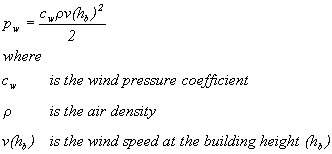
The wind pressure coefficients are defined in such a way that the wind
pressure on an aperture is -

See the Tas Theory manual for a detailed account of how the wind pressure coefficients are applied.
There are two buttons relating to the wind pressure co-efficient file:
Create
Creates a wind pressure co-efficient file. It will ask the user to enter the number of wind directions and then it will create a file with the correct number of rows and columns. The user must then edit the co-efficient values.
Edit
Opens the selected wind pressure co-efficient file in Notepad, allowing the user to edit the values.